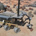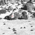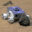

Fig. 1: A rover approaches the target on a rock using visual target tracking during autonomous navigation with hazard avoidance.
Automated target approach and instrument placement can significantly reduce surface operations time. Mars rover operations require multiple communication cycles, generally over a period of several sols (Martian days), to enable a rover to approach and place an instrument on a target rock up to 10 meters distant. It would be desirable to conduct the entire 10-m target approach and instrument placement with one cycle in a single sol. This improved capability will significantly increase the science return achievable within the life of a mission. JPL Robotics is working on three technologies to enable single-sol approach-and-placement operations:

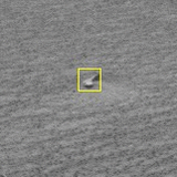
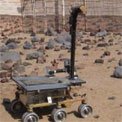
Fig. 2a: Visual target tracking updates the goal target-image position (red square) and its 3D position more accurately as the rover approaches the target from 10 m away (left) to 2 m away (right).
A rover pose estimator alone, including a visual odometer, does not provide sufficient accuracy for single-sol instrument placement. The visual target-tracking technology has been shown to provide sufficient accuracy but requires careful validation studies in terms of tracking reliability (success rate) and accuracy. Tracking should perform well even during winding rover motions for hazard avoidance. Several technology elements have been developed:
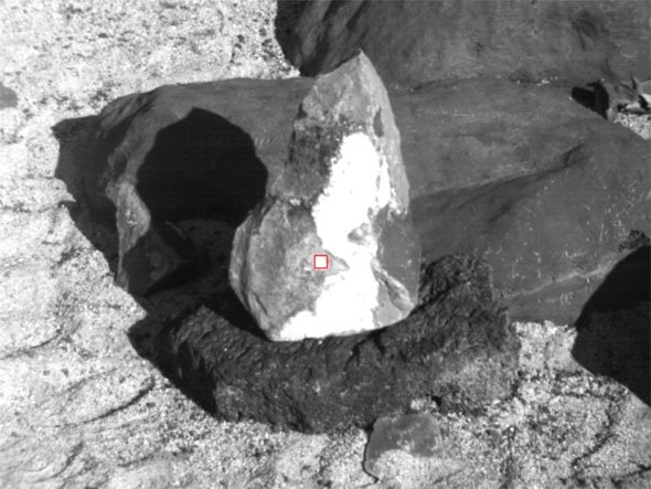
Fig. 2b: Visual target tracking updates the goal target-image position (red square) and its 3D position more accurately as the rover approaches the target from 10 m away (left) to 2 m away (right).
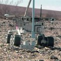
2. Rover-based manipulation to place an instrument with collision avoidance
After the rover reaches a target through visual tracking, the rover needs to be placed at a good location where the arm can be deployed to place an instrument. The rover needs to avoid hazards, and the arm needs to avoid collisions with the environment. Examples of technology elements developed for this capability include the following:

Fig. 3a: The rover moves to a base position that allows a collision-free arm path. Then the arm places an instrument on the designated target.
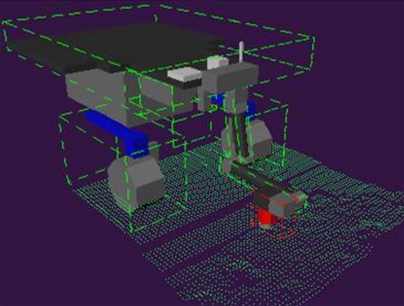
Fig. 3b: The rover moves to a base position that allows a collision-free arm path. Then the arm places an instrument on the designated target.
3. Vision-guided manipulation for accurate instrument placement
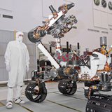
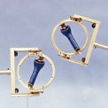
Accuracy of the final placement of the instrument on a target is enhanced with vision-guided manipulation. In vision-guided manipulation, the end-effector or instrument is tracked with cameras as it is guided to the target. The End-effector Position Error Compensation (EPEC) algorithm was developed to provide vision-guided manipulation for accurate instrument placement. The EPEC algorithm reduces the difference between the position of a fiducial (a trackable item) on the end-effector as determined by stereo vision and forward kinematics. The algorithm was tested on the Mars Exploration Rover mission Opportunity rover using the contact ring of the Mossbauer spectrometer as the fiducial. Results of one of the tests is shown in Figure 4.
Some of these technologies were infused into the MER flight software for real experiments on Mars during MER's extended mission. Others are planned for future mission infusion, increasing science operation capabilities, and enabling sample return.
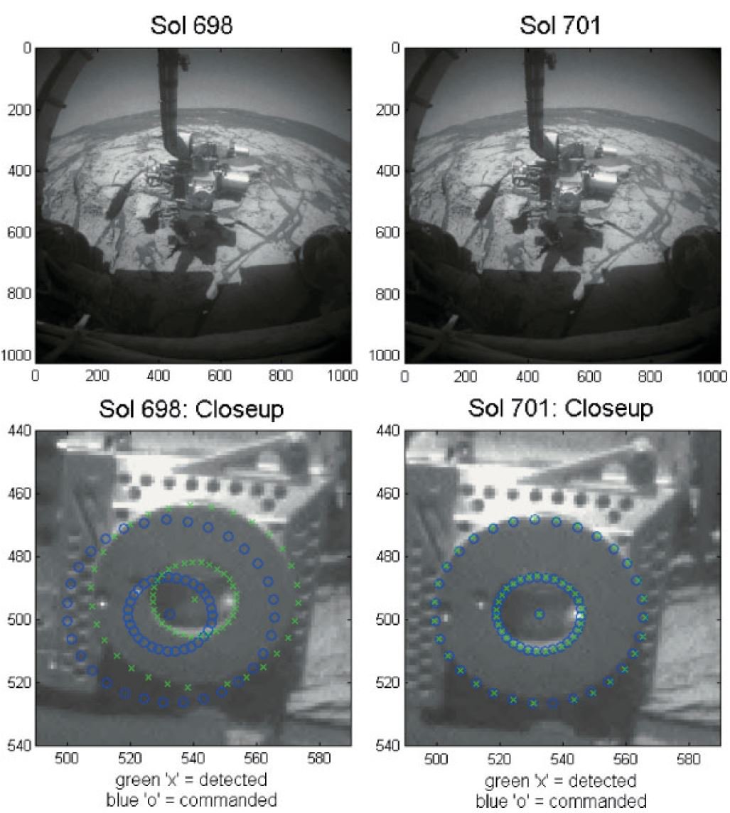
Figure 4: Application of EPEC vision guided manipulation on the Mars Exploration Rover mission Opportunity rover showing the commanded (blue circles) and detected (green x’s) fiducial locations before (sol 698) and after (sol 701) correction.